Every pipe, before we pour: how we coordinate MEP in 3D
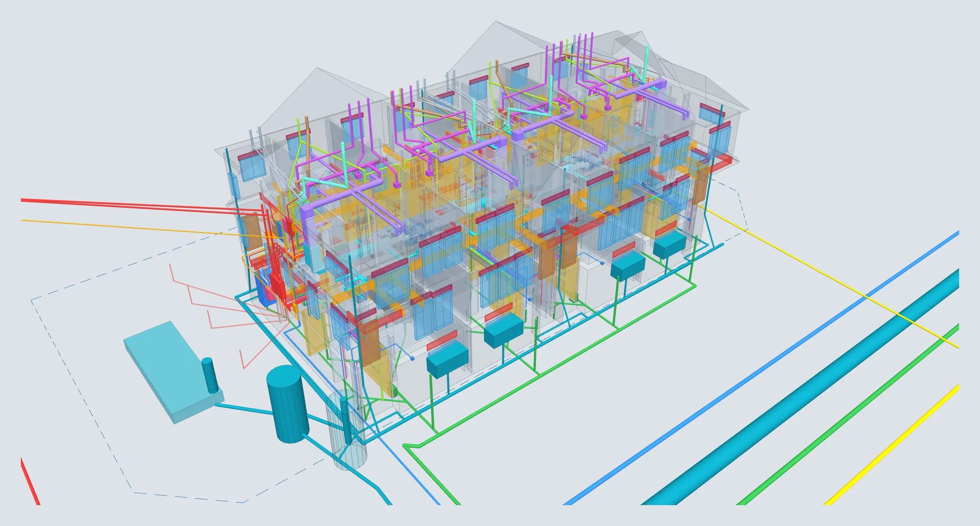
On a multi-family build, the expensive surprises rarely come from the big decisions. They come from a drain line that runs into a footing, a duct that needs to cross a beam that can’t be drilled, or a vent that ends up in the same attic space as a return-air duct. Found on site, each one means rework, delay and a change order.
So before we break ground on our Lynnwood 4+4, we build it in 3D first.
What goes into the model
We start from the stamped drawing set — architectural plans, sections and elevations, mechanical drawings, the site servicing plan, the floor-joist layout and the structural foundation drawings — and model every building system in place:
- Plumbing: cold and hot water, sanitary drains and vents for all eight homes
- Mechanical: supply and return air, HRV, outdoor air, bath fans, range hoods, flues and hydronic heating
- Electrical and communications: service entrance, feeders and telecom routing
- Gas and site services: water, sanitary and storm connections to the City mains, weeping tile and radon rough-in
- Structure: the floor joists, glulam beams, girders and headers that pipes and ducts must work around — plus the foundation reinforcing
Across the building that is more than 3 kilometres of pipe, duct and wire, and about 1,500 pieces of foundation rebar, each one placed where it actually needs to go.
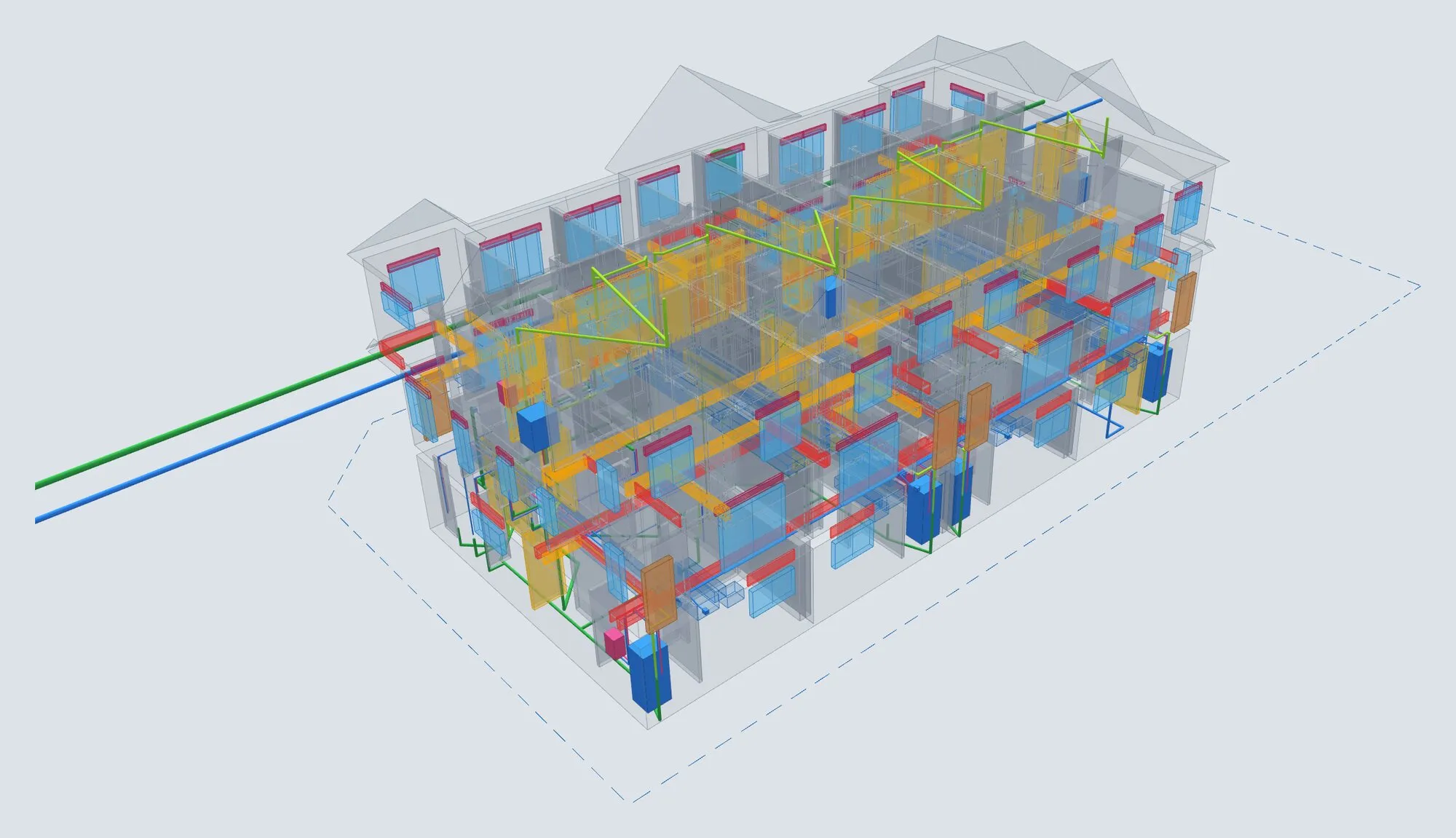
Solving clashes on screen, not on site
With everything in one model, conflicts become visible long before a trade shows up. On Lynnwood, coordination flagged 41 items to resolve before construction. A few examples of the kind of problems it caught:
- A building drain routed through the edge of a footing — rerouted to clear it
- A plumbing stack that would have landed on a party-wall footing — offset into a small chase instead
- An attic vent line running at the same height as a return-air duct — raised to pass over it
Every pipe that crosses a floor joist is checked against the joist manufacturer’s hole chart, and anything that meets a beam or header that can’t be drilled is routed below it. Walls that have to carry stacks and ducts are identified early and framed as 2×6 service walls or chases.
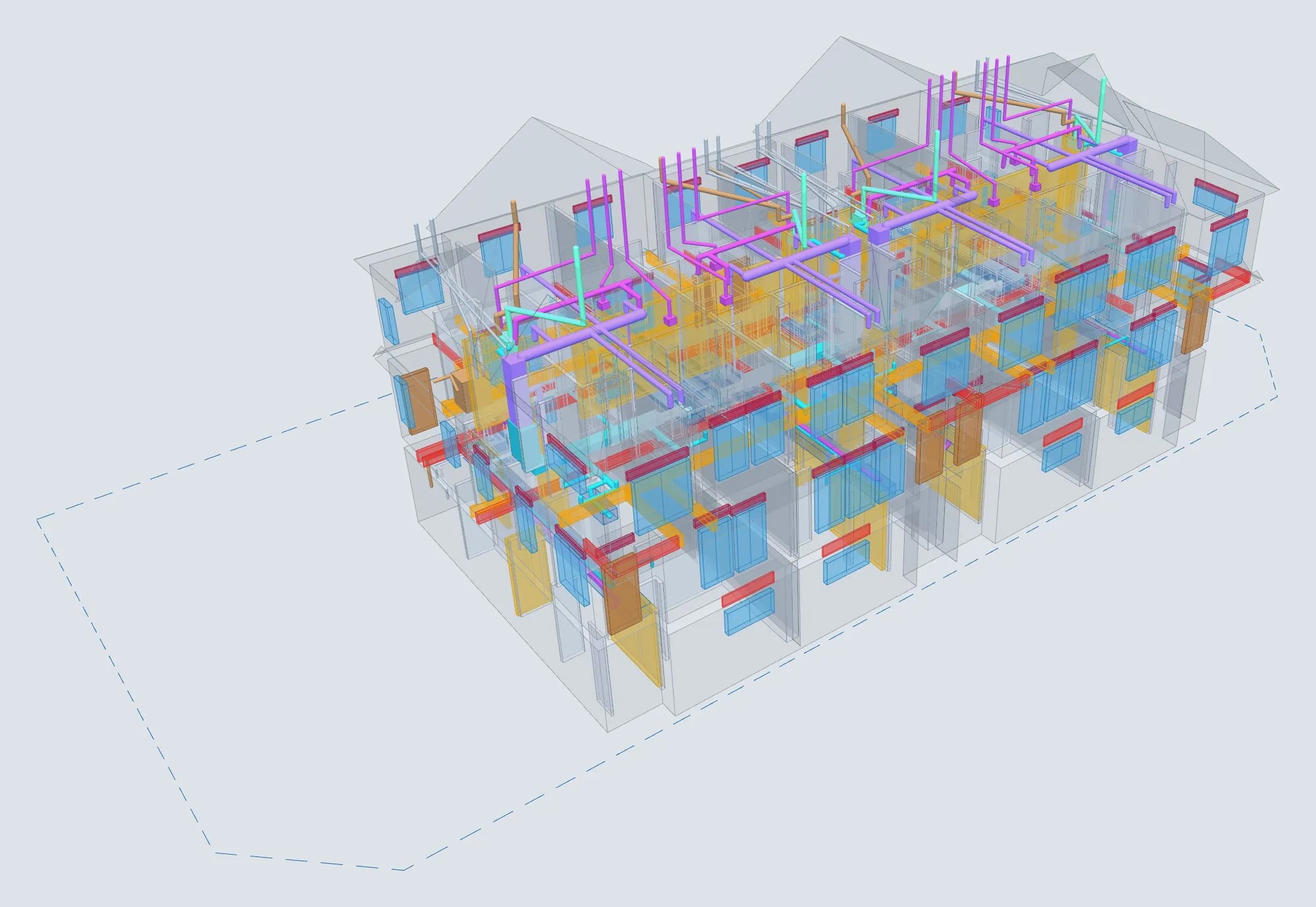
Why it matters to our clients
- Fewer change orders. Problems are solved with a mouse, not a saw.
- A cleaner schedule. Trades arrive to a plan that already works, instead of discovering conflicts in sequence.
- Better buildings. Ducts and drains get the straight, efficient runs they need, and ceilings don’t get lowered to hide a reroute.
- Clear communication. Owners, lenders and trades can all see exactly how the building goes together.
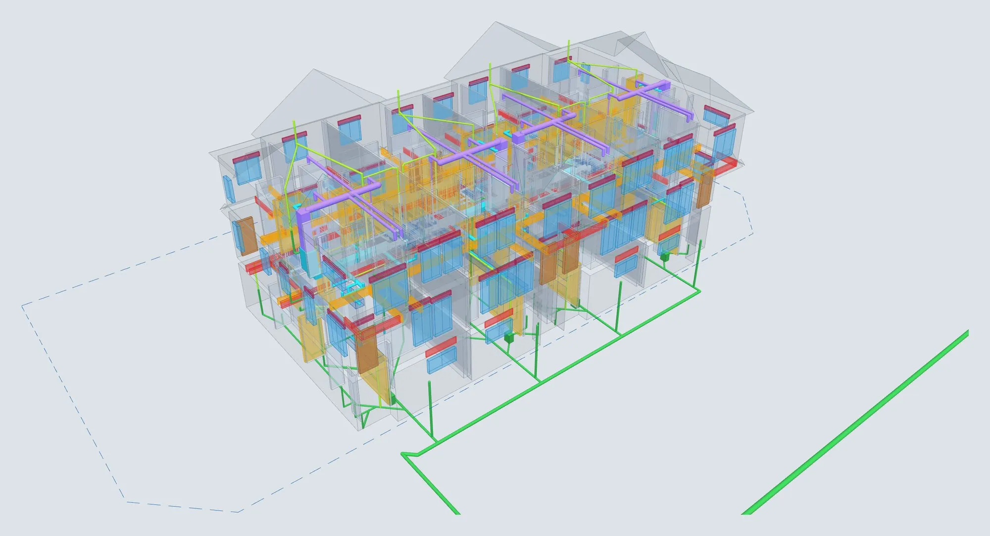
The model doesn’t replace each trade’s shop drawings or the permit set — it is how we make sure they all fit together before anyone cuts a hole.
Planning a multi-family or infill project? Talk to us about building it with a general contractor that coordinates every system before construction starts.